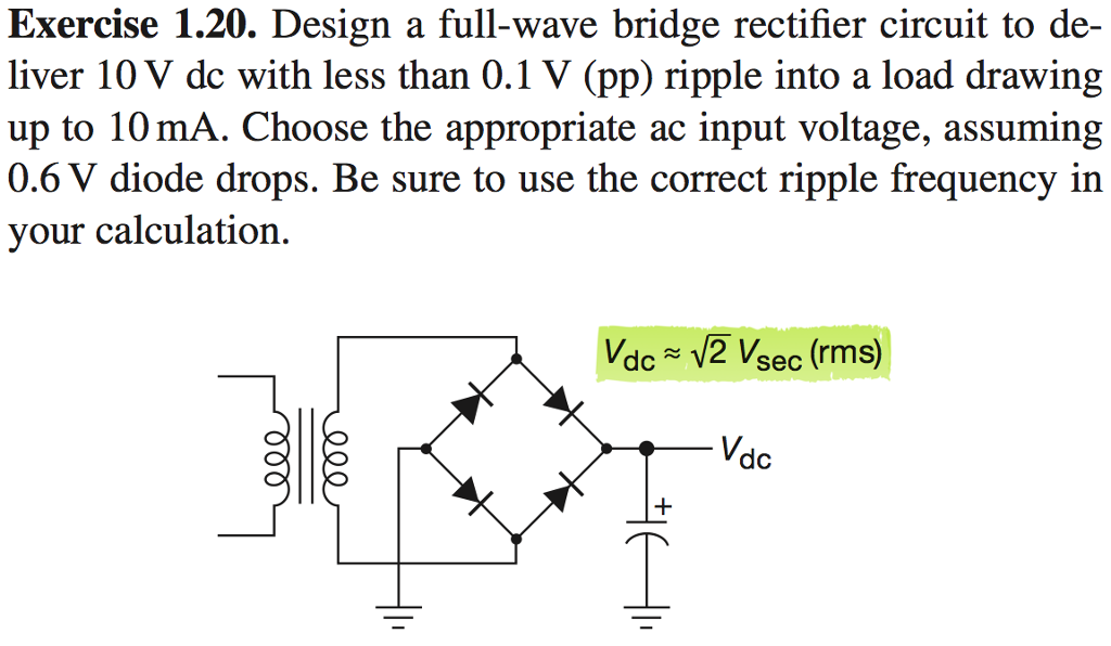
This complements the reservoir capacitor, C 1, with a series inductor, L 1, and a second filter capacitor, C 2 so that a steadier DC output can be obtained across the terminals of the final filter capacitor. To further reduce this ripple, an LC π-filter (pi-filter) such as shown in figure 6.6 can be used. For three-phase inputs a three-phase bridge will give six peaks per cycle and even higher numbers of peaks can be achieved by using transformer networks placed before the rectifier to convert to a higher phase order. A full wave rectifier, figure 6.5(b) achieves two peaks per cycle and this is the best that can be done with single-phase input.

Where: V rippleis the maximum ripple voltage on the DC outputį is the frequency of the ripple (generally 2X the AC frequency)Ī half-wave rectifier, figure 6.5(a) will only give one peak per cycle and for this and other reasons is only used in very small power supplies and where cost and complexity are of concern. The maximum ripple voltage present for a Full Wave Rectifier circuit is not only determined by the value of the smoothing capacitor but by the frequency and load current, and is calculated as: The load current and the supply frequency are generally outside the control of the designer of the rectifier system but the number of peaks per input cycle can be affected by the choice of rectifier design. In extreme cases where many rectifiers are loaded onto a power distribution circuit, it may prove difficult for the power distribution grid to maintain a correctly shaped sinusoidal voltage waveform.įor a given tolerable ripple the required capacitor size is proportional to the load current and inversely proportional to the supply frequency and the number of output peaks of the rectifier per input cycle. For a given load, R L, a larger capacitor will reduce ripple but will cost more and will create higher peak currents in the transformer secondary and in the supply feeding it.

Sizing of the filter capacitor, C 1, represents a tradeoff. Figure 6.5(b) Full-wave Rectifier RC-Filter


 0 kommentar(er)
